Guaranteed Higher Grade!
Free Quote

This assignment forms part of the formal assessment for this module. If you fail to reach the required standard for the assignment then you will be allowed to resubmit but a resubmission will only be eligible for a Pass grade, not a Merit or Distinction.You should therefore not submit the assignment until you are reasonably sure that you have completed it successfully. Seek your tutor's advice if unsure.
1) This question is about synchronous induction motors on infinite busbars. The exciter current induces a back emf (E) and the magnitude and angle of the current will depend on E’s magnitude.

2) This question uses construction skills to determine the machine characteristics. A three-phase delta-connected synchronous induction motor is connected to a 415 volt, 50 Hz supply. The winding resistance is negligible and the synchronous reactance per phase is 4 ohms. The input power is 25 kW and the motor has a leading power factor of 0.8.
iii) measure or calculate the magnitude of E
iii) Calculate or measure the load angle
3) This question is about induction motors. A wound rotor, induction motor has a rotor resistance of 0.6 ohms per phase and a rotor leakage reactance of 8 ohms.
4) This question is about the standard tests for determining the characteristics of a motor. The motor’s characteristics are tested using a two-stage process. The no load test and the locked rotor test. The results will populate the equivalent circuit shown in figure 2.

 Last-Minute Strategies for Academic Success
Online courses are time taking and complicated in nature. That is why students are advised to take
 150+ Humanities Research Topics that Captivate Scholars
As an academic who has spent more than a decade navigating the archives, evaluating student manuscr
 How to Write a Term Paper: The Ultimate 2026 Step-by-Step Guide
As a longtime academic mentor, I have watched thousands of college students face the exact same dau
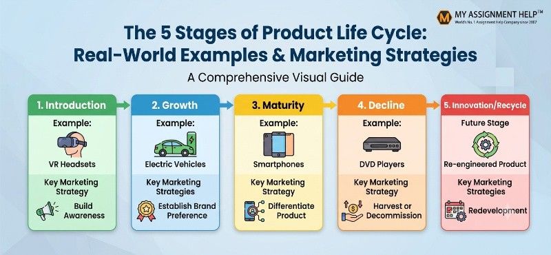 The 5 Stages of Product Life Cycle: Real-World Examples & Marketing Strategies
Every product you buy, use, or eventually throw away follows a predictable path. It emerges from a
