
Shear-Thinning and Shear Thickening Fluid Models
Questions:
VISCOSITY :Shear
1. (a) A yield stress material is found to be best described by the “Bingham-Plastic” model. Explain the terms which are required to represent the material in this model and suggest an alternative model for materials which display the following characteristics: shear-thinning, shear-thickening.
Illustrate your flow models using diagrams of shear stress against shear rate and apparent viscosity against shear rate. What are the limitations of the model when applied to shear-thinning fluids and can it be modified to account for a yield stress ? Your answer should refer to the following terms and define each of them: shear stress ; shear rate ; apparent viscosity ; zero-shear viscosity; consistency. Suggest a flow model for (i) shear-thinning, (ii) shear-thickening fluids and (iii) Newtonian fluids and explain your answer using appropriate diagrams of shear stress against shear rate and apparent viscosity against shear rate.
1. (b) A pressure drop of 105 N/m2 is developed when a fluid flows through a straight circular pipe 20 m in length and 25 mm in diameter. The fluid is Newtonian with a shear viscosity of 1 Pa s. A chemical is added to the fluid and its flow properties are changed. A graph of shear stress against shear rate and apparent viscosity against shear rate shows (i) that the changed fluid is shear-thinning, with a shear-thinning power-law index = 1/3 ; and (ii) that its apparent viscosity is the same as that of the original fluid at a shear rate of 1000 s-1. Calculate the volumetric flowrate for the shear-thinning fluid at the original value of the pressure drop.
1. (c) A power-law fluid has a density of 1075 kg/m3. It is pumped at a rate of 2500 kg/hour through a pipe of internal diameter 25 mm.The flow is laminar and the power law constants are K2 = 3 Pa.sn and n = 0.5. Estimate the pressure drop over a 10 m straight length of pipe and the centre-line velocity for these conditions.
2. (a) You are provided with information from a viscometer for 3 different fluids. The information consists of the results of measurements of shear stress for different values of shear rate. Using appropriate diagrams, explain how you would use this information to characterise the fluids in terms of their non-Newtonian flow characteristics according to (i) the Bingham-Plastic; (ii) the shear-thinning fluid and (iii) the shear-thickening fluid models, respectively. Suggest a suitable model for the shear-thinning fluid and discuss any limitations it may have.
2.(b) A material flows in a pipe of 0.15m diameter at a velocity of 0.5 ms-1. The relation between shear stress σ and shear rate ϒ is
σ = 2.5 ϒ 0.2 (SI Units)
As a result of temperature change the Power Law index becomes 0.25 but the apparent viscosity is unchanged when the shear rate is 100 s-1. Calculate the percentage increase in the mean velocity of the material at the same pressure drop and at the new temperature.
(b) A horizontal pipe of circular cross-section and 600 mm diameter carries water under a head of 30 m with a velocity of flow of 3 m s-1. If the pipe turns through a 75 degree bend, calculate the magnitude and direction of the resultant force on the bend.
NEWTON”S SECOND LAW:Bernoulli
1. (a) Explain how the Bernoulli Energy Equation can be obtained from considerations of the forces acting on a streamtube of fluid. Ensure that your answer explains the significance of the terms in the Equation and its limitations. What principle could be used to create a differential head flowmeter based on this Equation ?
1. (b) Water flows through a pipe of inside diameter 200 mm at a rate of 100 m3h-1. The flow abruptly enters a section which reduces the pipe diameter to 150 mm, for which the head loss is equivalent to 0.2 velocity heads based on the smaller pipe. If the gauge pressure is 80 kNm-2 upstream of the reducing section, find the force needed to hold the section in position.
2. (a) You are required to create a differential head flowmeter based on a convergence in a section of pipe. Starting with an expression for the forces acting on an ideal fluid, show how you would estimate the volumetric flowrate based on measurements of differential pressure. How would you modify your answer to account for the fact that a real fluid will have viscosity and how would you ensure that energy degradation is minimised?
2.(b) A manometer uses a manometric fluid of density 1075 kg/m3 to measure the pressure drop across an orifice plate with a throat diameter of 75 mm. The orifice plate is placed inside a vertical pipe with a diameter of 225 mm and oil with a density of 860 kg/m3 is flowing upwards inside the pipe. The deflection of the manometer fluid is 0.5 m and the discharge coefficient of the orifice is 0.659. What is the flowrate of the oil?
3. (a) Beginning with Newton’s Second Law calculate the force required to stabilise a 90o horizontal pipe bend against movement due to hydrodynamic reaction forces. State any assumptions you would make and explain how you would calculate the direction of the force.
3. (b) A jet of water of 22.5 cm diameter impinges normally on a flat plate moving at 0.6 m s-1 in the same direction as the jet. If the discharge is 0.14 m3 s-1 find the force and the work done per second on the plate.
4. (a) Explain how you would create a differential head flowmeter based on convergence at an orifice plate placed in a section of pipe. Starting with an expression for the forces acting on an ideal fluid, show how you would estimate the volumetric flowrate based on measurements of differential pressure.
4. (b) A horizontal venturi meter with a discharge coefficient of 0.96 is to be used to measure the flowrate of water up to 0.025m3s-1 in a pipe of internal diameter 100 mm. The meter is connected to a differential manometer containing mercury (Specific Gravity,SG = 13.6). If the maximum allowable difference in mercury levels is 80 cm, what is the diameter of the throat ?
5. (a) Using Newton’s Second Law as a starting point, explain how you would create a flowmeter based on a converging section of pipe for a real (non-ideal) fluid. Your answer must explain how the degradation of energy is minimised and how you would estimate the volumetric flowrate based on measurements of differential pressure.
5. (b) Obtain an expression for the force exerted by a jet of liquid which leaves a nozzle and strikes a stationary flat plate normally with a velocity v. How would this expression be modified if the plate were to be moving in the same direction as the jet with a velocity u ? Explain any assumptions which you make.
5. (c) Two pressure gauges are located at tapping points 50 cm apart on a vertical Venturi tube which has an inlet diameter of 150 mm, a throat diameter of 70 mm and a discharge coefficient of 0.98. If a liquid of density 1,000 kgm-3 flows upward through the Venturi tube at a rate of 0.075 m3s-1 what is the difference in reading of the two pressure gauges ?
5. (d) Droplets of oil (density = 960 kg/m3) are dispersed as an emulsion in a solution with a density and shear viscosity the same as water. Calculate how long an 80 µm spherical droplet will take to rise from the bottom of a tank to the surface 1.4 m above in still liquid. Neglect acceleration effects and state any assumptions you make.
RUSHTON TURBINE
1. (a) Explain what factors influence the amount of power input required for fluid agitation and mixing in a standard Rushton turbine. Use this mixer configuration to explain why scale-up under conditions of ‘same torque per unit volume’ is equivalent to performing scale-up at constant tip speed in the fully turbulent region of mixing. Explain why the ‘same mixing time criterion’ can be prohibitively expensive.
Limitations of Shear Thickening Fluid
1. (b). You are required to agitate water with a standard ‘Rushton’ turbine. The tank diameter is 2 m and you are required to work to a tip speed design criterion of 3 m s-1. Assuming a Power Number of 6, calculate:
(i) the power required per unit volume of fluid
(ii) the speed that the impeller should be driven at in a geometrically similar 4 m diameter tank on the basis of scale-up at equal power per unit volume
State any assumptions you make
2. (a) Describe the configuration of a standard Rushton turbine and use this mixer configuration to explain (i) why the ‘same torque per unit volume’ scale-up criterion is equivalent to performing scale-up at constant tip speed in the fully turbulent region of mixing; and (ii) why the conditions under which scale-up based on the ‘same mixing time criterion’ could prove very expensive.
(b). A horizontal pipe with an inside diameter of 200 mm has a 180o U-bend and carries a fluid of density 900 kgm-3 at a rate of 150 m3h-1. Find the force exerted by the liquid on the bend if the gauge pressures upstream and downstream of the bend are 100 kPa and 80 kPa, respectively.
3. (a) What are the main parameters influencing power input for fluid agitation and mixing. Explain why the ‘same mixing time’ scale-up criterion may be prohibitively expensive. Refer to the fully turbulent region of mixing and the standard ‘Rushton-Turbine’ configuration in your answer.
3(b). Tests on a small scale tank 0.3 m in diameter show that a blending process between two miscible liquids (both aqueous with properties the same as water) is complete after 1 minute when using an impeller speed of 250 revolutions per minute.
It is decided to scale up the process to a tank of 2.5 m diameter using the criterion of constant tip speed.
(i) What speed should be chosen for the larger impeller ?
(ii) What power will be required ?
(iii) What will be the blend time in the large tank ?
State any assumptions you make. Assume a standard Rushton-turbine configuration, and a Power Number of 6.
LAMINAR/TURBULENT FLOW: Reynold’s Number
1. (a) Explain the meaning of the terms ‘friction factor’, ‘Reynold’s Number’ and ‘relative roughness’ and how they are used in the construction of the Moody plot. Verify the relationship between friction factor and Reynold’s Number given in the Moody plot for the laminar flow region.
1. (b) A foam consists of droplets of oil (density 960 kg/m3) which are dispersed as an emulsion in a solution whose density and viscosity is the same as water. Calculate how long an 80 micron diameter ( 1 µm = 1 x 10⁻⁶ m ) spherical drop will take to rise from the bottom of a tank to the surface 1.4 m above in a still liquid (neglect acceleration effects).
2. (a) The flow of a viscous fluid past a spherical particle is characterised by the Reynold’s Number, Re’. Explain the form of the curve obtained when Re’ is plotted against the Drag Coefficient. Ensure that your answer includes:
(i) an explanation of the terms involved in Re’ and the Drag Coefficient,
(ii) an explanation of the term 'separation',
(iii) an account of the changing drag force, F, on the particle.
2. (b) A water softener consists of a vertical cylindrical pipe 0.5 m long and 50 mm internal diameter packed with an ion-exchange resin consisting of spherical particles whose diameter is 1 mm. The bed porosity ε is 0.33. The column runs full of water, under a head of 0.2 m, but water trickles out slowly from the bottom of the column which is supported by a perforated plate. Calculate the flowrate and verify any assumptions which you make.
Bernoulli Energy Equation and Its Application in Fluid Mechanics
1. a)
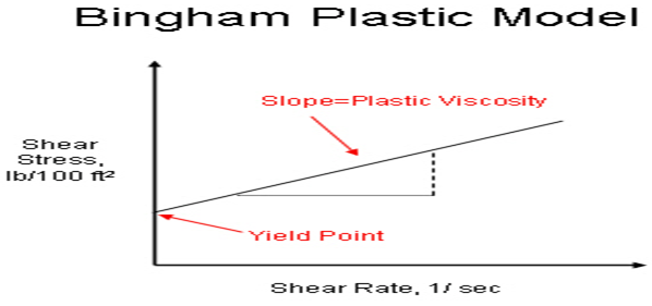
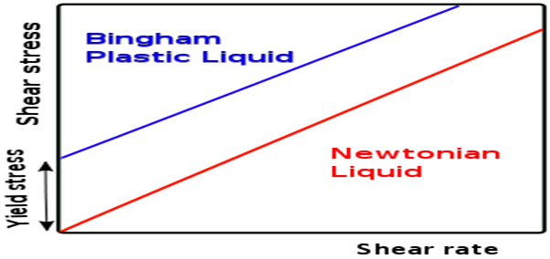
Bingham plastic can be defined as such kind of viscoplastic materials which acts as the rigid body at minimum stresses and acts as the viscous flow at maximum stresses. It is widely used in drilling engineering for model of mathematical flow of the mud. The Bingham plastic model has been showcased below;
The alternative model is Carreau model which displays the shear-thinning and shear thickening characteristics of the model. The Carreau model is such kind of Newtonian generalized fluid where the viscosity of the material always depends on rate of shear of the material. The equation of the Carreau model is given by,
![]() , where the material coefficients are n, λ and is the viscosity at zero rate, is the viscosity at the shear rate of infinite, relaxation time is λ and n is the power index.
, where the material coefficients are n, λ and is the viscosity at zero rate, is the viscosity at the shear rate of infinite, relaxation time is λ and n is the power index.
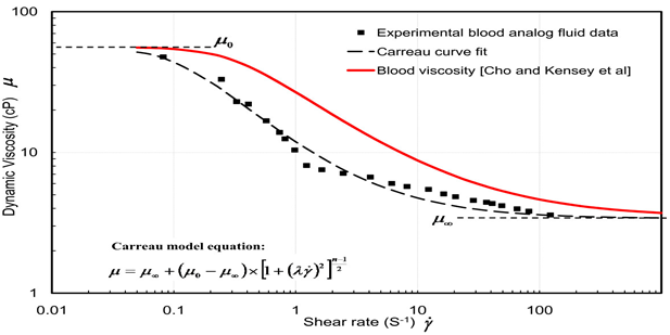
The above diagram showcases the graph plot between the shear rate and the dynamic viscosity. The equation, µ = K( Ë™γ)n−1 is given then reduced form of the Carreau model where k is consistency factor. The above plot depicts the relationship between the shear rate and the viscosity. The plot showcases the decreases of the viscosity of the fluid of shear thinning materials with the increasing of the shear rate.
The limitation of the model is that it cannot be fitted for any kind of polymer solutions in minimum and maximum shear range. The ranges between the lower and higher shear ranges showcase the zero shear viscosity and the infinite values of shear viscosity. This kind of model is best suited for the medium level of the polymer industry.
i) Shear thinning model
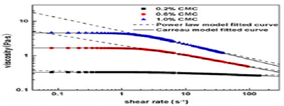
The above diagram showcases the shear thinning model which describes the plot between the viscosity and the shear rate.
ii) Shear thickening model
Herchel-Bulkley fluid model showcases the shear thickening condition of the viscosity.
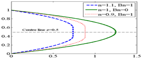
The plot showcases the relationship between the shear rate and the viscosity in Herchel-Bulkley fluid model.
iii) Newtonian fluids
The example of Newtonian fluids is the Bingham model which is described below in the plot.
b)
The volumetric flow arte equation is given by, (8u/D= 4Q/πR^3) = 8*1/3 /25 =4Q/ 3.14*(0.02)^3= 6.70*10^-7 m^3/s.
c)
The flow characteristics is denoted by, 8u/D = 8 / 25 = 0.32 s^-1
(8u/D)n-1 = 0.32 (0.5-1)= 1.76s
μ ap = K’(8u/D)^-0.5 = 3*0.32^-0.5=1.020 Pa s
And Re = φuD/ μ ap = 25*1/1.020= 24.50
So, the pressure drop is given by, ∆PF = 4f(L/di) φu2 /2 = 2*0.0075(25)*0.01/25 = 1.5 Pa.
2. a)
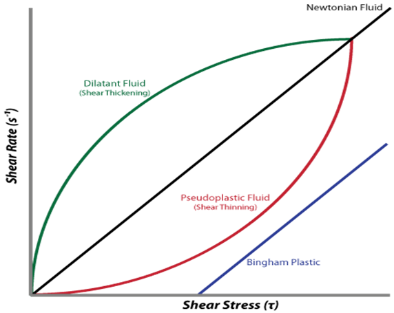
The above diagram depicts the plot between shear rate and the shear stress of the three kinds of fluids such as shear thickening, shear thinning and the Bingham plastic. Shear thickening plot showcases that the rate of the shear increases with the increasing of the dilatants fluid. The shear thinning fluid can be called as the Pseudo plastic fluid materials. The Bingham plastic graph plot does not pass through origin point of the graph.
Venturis, Nossles, and Orifices in Flowrate Measurement
The limitation of shear thickening fluid that it cannot pass through any kinds of solutions.
b)
The calculation is given by, ϑ= μ/P = 100/2.5 = 40*100 = 4000 m/s
c)
FX = -P1A1 - P2A2 cos(b) - d Q [V1 + V2 cos(b)] and Fy = P2 A2 sin(b) + d V2 Q sin(b) so, F can be denoted as F= (Fx2 + Fy2)1/2 , FX = 706.5*sin(75) = 682.42
The Bernoulli Energy Equation is stated that the motion of fluid is increase by decreasing its pressure or its potential energy. The mathematical expression of Bernoulli’s theorem is like:
PV+ m/2v2 = Constant, This is a correct statement to proceed with steam fluid for different cross sectional areas. Now the volume V at any point of this steam flow is the sum of its kinetic energy and potential energy. The equation looks like that
V= mv2/2 + PV
Now the energy of a fluid is moving from one point to another point with same motion then its energy equation is like
P1V+mv12 = P2V +mv22
By using m=ρv, Bernoulli energy equation can obtain, that is:
P1-p2 = ρ/2(v22 –v11)
This equation derives the Bernoulli energy equation with the help of Newton’s second law.
This theorem is used in fluid mechanics for steady streamline regions of flow. It can control the motion of fluid by decreasing the pressure of air or potential energy of fluid.
The Bernoulli theorem is limited for heat transformation of a particle including its mechanical transformation. This theorem will reduce the thermal energy.
With the help of nonlinear relationship in between flow and pressure, an accuracy of flow measurement can change the pressure of flow meter. This common relationship in between pressure and fluid flow can control the flow meter pressure. This is a successful approach of Bernoulli’s theorem to create the main principle of flow meter.
b)
The velocity for larger and smaller pipes is
V1= 4Q/3.14d12
= 4*100/3600/3.14*0.22
= 0.884 ms -1
And
V2= 1.67 ms -1
This is the head loss based on the velocity of smaller pipe
HL= 0.2 * 1.57^2/2g= 0.025
The pressure in 200 mm diameter including 80kNm-2 including 150 mm diameter pipe is found by applying Bernoulli’s equation
P2= P1 + ρ/2(V12 +V22) – ρgHL
= 80 * 10^3 +500*(0.884^2-1.57^2) – 1000*g*0.025
= 78.913 Nm-2
The upstream and downstream pressure are, P1a1 = 2513 N
And
P2a2 = 1394 N
The force in the X direction is
FX = 1000* 100/3600*(1.57-0.884) – 2513 + 1394
= -1100 N
So, 1.1 kNm-2 is the opposite direction to hold the reducing sector in position.
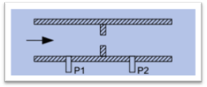
2. a)
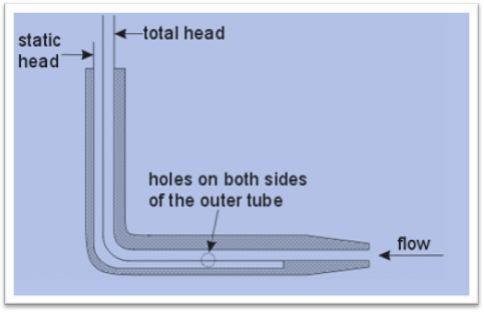
Figure: section of a pipe
Here static head = P/y
Dynamic head = (P/y + v^2/2g)
Procedures
• Venturis
• Nossles
• Orifices
It depends on
• Flowrate
• Fluid properties
• Element geometry
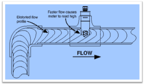
Figure: flow meter based on pipe
Bernoulli’s equation of energy conservation
P1 + 1/2 1U12 =P2 + 1/2 2U22 = constant =P0
P0 = total pressure at medium
Total sum of dynamic and static pressure is same throughout the whole pipe
p = P1 – P2 =/2(U22 –U12)
Volumetric flow rate is defined as Q
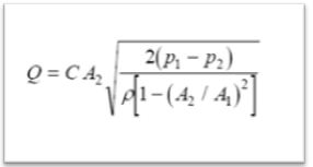
A1 = pipe’s area
A2= pipe’s flow area
P1 = upstream pressure
P2 = restriction pressure
= density
C= correction factor
Viscosity of fluid is basically the measurement of the resistance to steady deformation by tensile stress or shear stress. Real fluid has also effected by tensile stress and shear stress. So it is ensured that fluid has viscosity.
From the Bernoulli’s equation it is ensured that the degradation of energy is minimized.
b)
Density of manometric fluid = 1075 kg/m3
Diameter = 75 mm
The diameter of orifice plate = 225 mm
Density of orifice plate = 860 kg/ m3
Deflection of manometer fluid = 0.5 m
Discharge coefficient of the orifice = 0.659
Flow rate of the oil = Q = VA
= V * πD2/4 [A = πD2/4]
Where Q = flow rate
V= Viscosity
A = Area
D= Diameter of the pipe
Flow rate of oil = 0.5*π* 2252/4 – 0.659* π* 752/4
= π/4(0.5 * 2252 – 0.659 * 752)
= 16969.019 mm
= 16.969 m3 s-1
The flow rate of oil is 16.97 m3 s-1
3. a)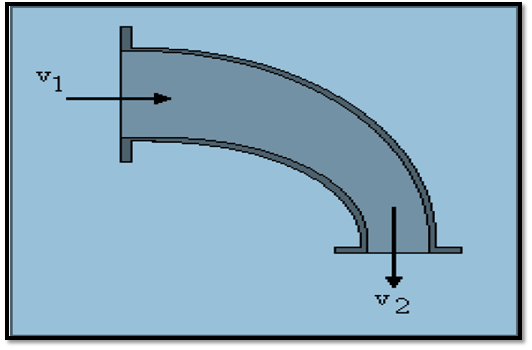
The pressure required to stabilize the pipe against movement is done by applying Bernoulli in between V1 and V2 points is as follows
P1 + ½ ρV12 = p2 + ½ ρV12
So the pressure forces
Fpx1 = p1A1 = 1200 N
Fpy2 = p2A2
Assume the inlet pressure of V1 is 4m/s and the outlet pressure V2 is 16 m/s
So the direction will go through from inlet pressure to outlet pressure that is from V1 to V2
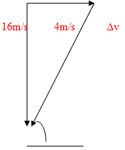
So, ∆v = (4^2 + 16^2)
= 16.49 m/s
And Fm = m2∆v= 659.7 N
Now the pressure for resolve section
Fmy = 659.7 sin 75.96 = 640 N
Fmx = 659.7 cos 75.96 = 160 N
So, the total force is acting at X direction is, 1200+160= 1360 N
The force acting at y direction = 0 + 640= 640 N
Here no initial force is acting towards Y direction so the direction of the actual force is acting towards X Axis.
b)The resulting force of the jet is F= m v1 {2(1-cosѲ)} ½
F = 45 N
4 a)
A differential head flow meter based on convergence at an orifice plate placed in a section of pipe
Here P = Pressure
D = Density
Q = Flow rate
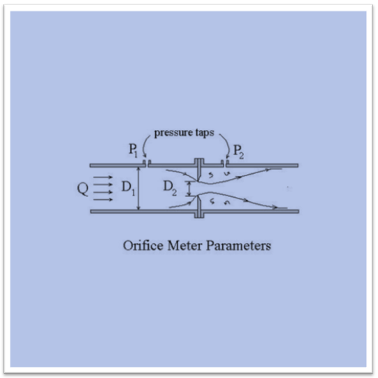
Flow meter is basically a process which is used to determine the volume of the gas which is passing through the nozzle with the per unit time. The creation of differential head flow meter is depended on three procedures. These procedures are basically Venturis procedure, Nozzles procedure and Orifices procedure. The orifice procedure is dependent on the Flow rate of the fluid, various properties of the fluid and the geometry of element.
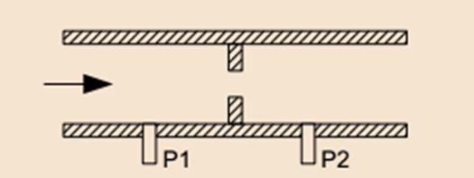
Figure: Orifice meter pipe
The volumetric flow rate is basically defined by the below equation:
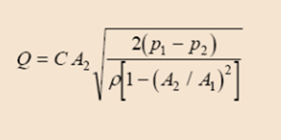
Q= flow rate
C= correction factor
= density
A1 = pipe’s area
A2= flow area of the pipe
P1 = upstream pressure
P2 = restriction pressure
b)
Discharge coefficient of venture meter = 0.96
Flow rate of water = 0.025 m3 s-1
Internal diameter = 100 mm
Specific gravity = 13.6
Maximum difference = 80 cm [in mercury]
The equation of flow rate
Q = u2A2 = Cd √ {2R (pm – p) g/p}* A1A2/√ (A12 – A22)
Where A= Area
P = density
G= gravity
A2 = 13.6 *√ 2* 80/0.025 * 1002
= 33 meter
The diameter of the throat is 33 meter.
5. a)The most common flow meter is obtained from Newton’s second law. In numerical form the common formula is written as: m1 = m2
= A1V1/v2 or A2V2/v1
If the V is constant then the equation is simplified to a new form A1V1= A2V2
Using Bernoulli’s theorem the flow meter of a pipe for a real fluid is represented as V1
A1= V2A2 or V1= A2V2 /A1
b)Suppose a Nozzle has a n inlet area is 0.005 m2 and the discharge diameter is combined with its atmosphere. The gauge bar including inlet of the nozzle is 3 Bar. Since the area of vertical place is coming from Fv =0 by using gauge pressures, so the final force is Zero at exit point.
Fpx2 = 0, so FH = 1500 – 0= 1500 N to the right angle.
c)The Bernoulli’s equation has been stated below,
p1/+v12/2g=p2/g+v22/2g+z2
Continuity equation has been mentioned below,
A1v1=a2v2
After the rearrangement equation of the differential pressure has bee stated below,
P1-p2=g(v1^2/2g((a1/a2)^2-1)+z2-z1)
Equation of the flow rate is
Q=Cdav1
Differences between two pressure gauges=
P1-P2=500x (.075/(.98x3, 141x.15^2/4) ^2x ((.15/.07)^4-1)+2x9.8x.5)
=290,232.18 NRA^-2
=2902 KNm-^2
1. a)
The factors are the Reynolds number, power number, flow meter and the blend time of the dimensionless. Scale up under the conditions of same torque per unit volume is equivalent to performing scale up at the constant speed in the turbulent region of mixing because, torque per volume can be termed as the mixing intensity in fluid velocities and it related to the effective motion of the mixer.
b) i)
The equation is given by,
Where P0 is the dimensionless power number, N is the speed of the rotational,
ρ is the fluid density. So, P= 6*3^3*2 = 324 Pa
ii)
so, N^3 = P/p0 ρ D^5 = 324/(6*4^5)= 0.03 m/s where, Where P0 is the dimensionless power number, N is the speed of the rotational, ρ is the fluid density.
2. a)
The factors are the Reynolds number, power number, flow meter and the blend time of the dimensionless. Scale up under the conditions of same torque per unit volume is equivalent to performing scale up at the constant speed in the turbulent region of mixing because, torque per volume can be termed as the mixing intensity in fluid velocities and it related to the effective motion of the mixer.
b)
The equation is given by, FX = -P1A1 - P2A2 cos(b) - d Q [V1 + V2 cos(b)] and Fy = P2 A2 sin(b) + d V2 Q sin(b)
FX = -100*200- 80*200cos (180)- 150(900)= -139000 Fy = 0 so, F = 139000 pa
3. a)
The main parameters are which influencing the power input for the agitation and mixing of the fluids are mixing time and the circulation time. The ‘same mixing time’ scale-up criterion may be prohibitively expensive because of larger tank mixture.
b) i)
The required speed can be calculated by, N^3 = P/p0 ρ D^5 = 100/(6*0.3^5) = 5.29*10^-5
ii) The required power can be calculated by, = 6*250 30.3^5 = 227812.5 Pa
iii) So, the required blend time can be calculated by, 227812.5 * 5.29*10^-5*227812.5^-(1.69/5.29) = 0.234
1. a)
The head loss or various pressure losses due to the loss of the friction can be called as the friction factor. Friction factor can also be referred to as the Darcy friction factor or the Moody friction factor.
Renolds number can be defined as such kind of dimensionless quantities which can help to predict the similar kinds of flow patterns in various fluid situations.
The ratio between the roughness of the duct and the diameter of the hydraulic can be referred to as the relative roughness. Which can be expressed as r = k / dh
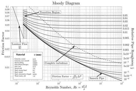 The above diagram depicts the moody plot between the friction factor and the Reynolds number.
b) The length of the oil droplet can be calculated by, mg= ∏ d γ
Where m is the mass of the oil droplets, d is diameter of the droplet and γ is length of the droplet. So, volume can be calculated by, 4/3 ∏ r3 = 4/3*3.41*(80*10^-4) = 0.036 m^3
So, length can be calculated by, 0.036/ (3.41* 80*10^-4) = 1.31
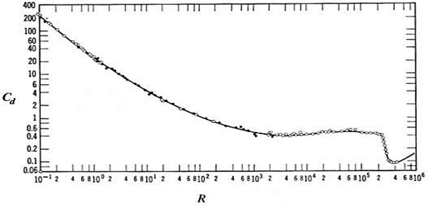
The above plot showcases the relationship between the Reynolds number and the drag coefficient.
The separation can be termed as the relationship between the removal of the impurities and the components of the substances.
b)Flow rate can be calculated by, ¼*∏ (pipe diameter) 2* velocity = ¼ *3.14*(50)2* 0.33 = 647.625
References
Bourne, M. (2002). Food texture and viscosity. San Diego: Academic Press.
Bowdler, D. and Leventhall, H. (2011). Wind turbine noise. Brentwood, Essex: Multi-Science Pub.
Boyce, M. (2006). Gas turbine engineering handbook. Boston: Gulf Professional Pub.
Chapman, S. and Cowling, T. (1970). The mathematical theory of non-uniform gases. [Cambridge, Eng.]: Cambridge University Press.
Cohen, H., Rogers, G. and Saravanamuttoo, H. (1987). Gas turbine theory. Burnt Mill, Harlow, Essex, England: Longman Scientific & Technical.
Du Bois, W. (1996). The souls of Black folk. Charlottesville, Va.: University of Virginia Library.
Falcone, M. and Makridakis, C. (2001). Numerical methods for viscosity solutions and applications. Singapore: World Scientific.
Fleming, W. and Soner, H. (2006). Controlled Markov processes and viscosity solutions. New York: Springer.
Fowler, H. and Gowers, E. (1965). A dictionary of modern English usage. New York: Oxford Univ. Press.
Giampaolo, T. (2006). Gas turbine handbook. Lilburn, GA: Fairmount Press.
Glasstone, S., Laidler, K. and Eyring, H. (1941). The theory of rate processes. New York: McGraw-Hill Book Company.
Hudson, W. (n.d.). Green mansions. Champaign, Ill.: Project Gutenberg.
King, P. (1981). The turbine. [Dunedin, N.Z.: P. King.
Lefebvre, A. (1983). Gas turbine combustion. Washington: Hemisphere Pub. Corp.
Maugham, W. (1936). Of human bondage. Garden City, N.Y.: Doubleday.
Maugham, W. (1995). The moon and sixpence. Champaign, Ill.: Project Gutenberg.
Neilson, R. (1902). The steam turbine. London: Longmans, Green, and Co.
Oates, G. (1997). Aerothermodynamics of gas turbine and rocket propulsion. Reston, VA: American Institute of Aeronautics and Astronautics.
Philbrick, W. (2009). The mostly true adventures of Homer P. Figg. New York: Blue Sky Press.
Tuchman, B. (1962). The guns of August. New York: Macmillan.
Tuchman, B. (1978). A distant mirror. New York: Knopf.
TURBINE., (1904). Die Turbine. Zeitschrift für modernen Schnellbetrieb, für Dampf-, Gas-, Wind- & Wasserturbinen. (Organ der Turbinentechnischen Gesellschaft.) Jahrg. 1. Hft. 1-Jahrg. 9. Hft. 24. Okt. 1904-Sept. 1913. Berlin.
Walsh, P. and Fletcher, P. (1998). Gas turbine performance. Oxford: Blackwell Science.
Yeats, W. (1956). The collected poems of W.B. Yeats. New York: Macmillan.
To export a reference to this article please select a referencing stye below:
My Assignment Help. (2016). Bingham Plastic And Carreau Model In Fluid Mechanics. Retrieved from https://myassignmenthelp.com/free-samples/fluid-flow-viscosity-shear.
"Bingham Plastic And Carreau Model In Fluid Mechanics." My Assignment Help, 2016, https://myassignmenthelp.com/free-samples/fluid-flow-viscosity-shear.
My Assignment Help (2016) Bingham Plastic And Carreau Model In Fluid Mechanics [Online]. Available from: https://myassignmenthelp.com/free-samples/fluid-flow-viscosity-shear
[Accessed 31 May 2025].
My Assignment Help. 'Bingham Plastic And Carreau Model In Fluid Mechanics' (My Assignment Help, 2016) <https://myassignmenthelp.com/free-samples/fluid-flow-viscosity-shear> accessed 31 May 2025.
My Assignment Help. Bingham Plastic And Carreau Model In Fluid Mechanics [Internet]. My Assignment Help. 2016 [cited 31 May 2025]. Available from: https://myassignmenthelp.com/free-samples/fluid-flow-viscosity-shear.